I have been a rocketeer for many years with the typical hiatus during early adulthood. Several years ago I came back to the hobby and launch mostly mid and high power stuff, but many times I am asked to conduct launches for local Cub Scout groups as well as my own children.
I wanted a multiple pad controller like our Tripoli club had, but did not need the capacity they had. A smaller version would work well with the Cub Scout launches and would be simple enough for our family launches.
My requirements:
- A launch controller that could handle 4-6 pads.
- Use high amperage relays to dump current to the igniters.
- Use easy-to-obtain serial cable of various lengths(10, 25, 50,100 ft).
- Capable of lighting A - J motors.
- Compact
- Reliable
The Internet being what it is, I set out on a quest for plans detailing a simple Multiple-Pad Launch Controller that even I could wire without screwing up. I consider myself quite technology savvy, but when I have to figure out a wiring diagram and then actually start soldering things together, something's bound to end up in smoke.
I found a system that was close to what I wanted, but it had one major drawback. The operator had to initially select a pad and then throw multiple switches to launch more than one rocket. I wanted something that was one switch per pad and hit fire. I later found this to be the hurdle - stay tuned.
Initially, I prototyped the controller mentioned in the previous paragraph. It had all sorts of continuity circuits, buzzers, etc, and every time I wired it, something went up in smoke - oops. See, I told ya. I set this prototype to the side for many months and did other things.
My rocket group, Tripoli Oklahoma, had to refurbish one of our relay boxes and it gave me a good look at the innards of that box. One day, on a whim, with all of my previously purchased components, I started putting things together with test leads. A test lead is just a wire with alligator clips at either end. I kept it simple.
After attaching a 12 volt hobby battery, I clicked on the "master arming" switch. The red LED came on and viola, no smoke. I next threw the "pad select" switch. Again, no smoke, and a pretty LED let me know the pad was selected. Finally, I hit the "fire" switch. The LED I had wired blinked every time I pressed the fire button - and no smoke. I finally made the circuit work!!!
Bolstered by my controller's success, I started drawing the diagram for it and started to figure out where and how multiple pads would fit in. Below is the diagram for a single pad circuit. Simple and easy.


I then figured out how multiple pads would fit in. Here is the diagram for multiple pads.
|
|
|
Figure 1 - Relay Box |
|
|
|
|
|
|
Figure 2 - Controller Box
|
The key component to make the multiple pad controller function as I wanted was a specific switch to select the individual pad circuits. It has to be a Double-Pole, Single-Throw(DPST). With a single throw of the switch, part of the circuit lights an LED, indicating that that pad is selected without sending a signal down the control cable. The other pole, is energized when the "Fire" button is pressed and sends a signal(current) down the serial cable to the appropriate relay - thus energizing the right igniter. If you use a SPST switch, the LED will only light when the "Fire" button is pressed - not too useful to see which pads are selected.
I used a DB9 serial cable for signaling the remote relay box and its circuits. A DB9 cable is lightweight, easy to solder, comes in many lengths, and can support up to a 8 pads without continuity(8 pads + 1 ground). A DB25 cable would be another good choice, and could support additional features like continuity along with 8+ pads.
Below are construction photos.
|
Click to Enlarge Photos
|
|
|
|
 |
|
 |
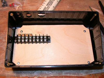
| Box with mounting plate and 1st terminal strip. |
|
Negative in, wired to 10A fuse then to terminal block(4 positions on left). |
|
|
|
 |
|
 |
| Lower area complete with positive in(feeds to lid term block, DB9 wired to 4 right positions of term block. |
|
Lid with holes drilled and filed. (Master arm on right side) |
|
|
|
 |
|
 |
| Lid with switches mounted. Temporary screws in center. |
|
Underside of lid with wiring up to pad select switches, Note circuit board and upper term block wiring, jumpers and standoffs. |
|
|
|
 |
|
 |
| Underside of lid complete. |
|
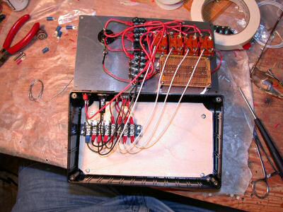
Lid connections to lower portion of box. |
|
|
|
 |
|
 |
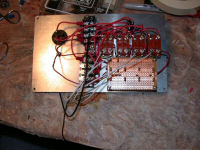
| Relay box innards. Top term strip feeds positive power through relay. Middle term strip feed negative to plugs on lid. Lower strip is a common negative signal from the relays and back to control box via DB9. |
|
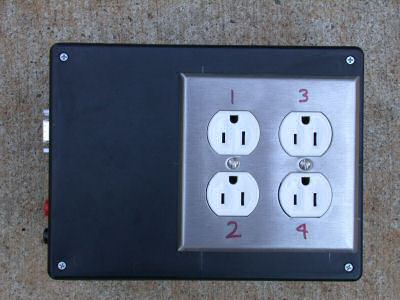
Relay box showing plugs in lid. |
|
|
|
 |
|
 |
| Relay box finished. |
|
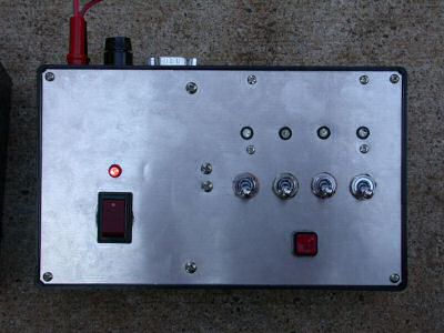
Controller box complete. |
|
|
|
 |
|
 |
| Controller box showing red armed LED. |
|
Controller box showing armed LED and one pad selected. |
|
|
|
 |
|
 |
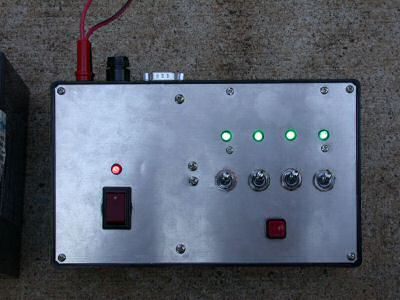
| Controller box showing armed LED and all four pads selected. |
|
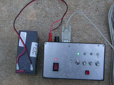
Wide view of controller box showing armed and one pad selected, battery and serial cable. |
|
|
|
 |
|
 |
| Wide view of relay box showing serial cable, battery, and ignitor lead. |
|
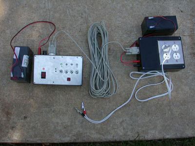
Overal system shot, showing both control and relay boxes, serial cable, batteries and ignitor lead. |
|
|
|
Things I'd like to do . . . Things I might do.
- Using one wire(positive and use existing ground) of my cable, I might wire a piezo buzzer into the relay box that would sound if the master arming switch is selected "On," and would warn someone that the system is armed while they are at the pads.
- Another addition could be a circuit(piezo or light) to warn users if a relay was "welded" closed and the igniter is "hot" without the Fire switch being pressed.
- I may substitute a key switch instead of the rocker switch for added security from inadvertent arming. The key switch I had was too big to fit my box and I could not find the two others I have . . . somewhere.
All of the components in the project were purchased from either Radio Shack or Digi-Key. Digi-Key is a LARGE electrical part supplier and will have just about anything you may need. All Electronics is another good parts house.
The most difficult part of the build was finding a box big enough to house the wiring without breaking the bank. I bought the largest plastic box I could find in the Digi-Key catalog. Other, larger boxes were available, but they were all metal(nice) and expensive - $35 and up.
Although, I could have wired the boxes more efficiently and saved space, I tried to keep things neat and reduce stress on components when opening and closing the cases. This is why I used terminal strips wherever I could.
Parts List
| Qty |
|
Description |
Supplier |
Part # |
|
Cost |
|
Total Cost |
| 1 |
|
Project Box. 8x7x3, Relay Box |
Radio Shack |
270-1809 |
|
6.99 |
|
6.99 |
| 1 |
|
Hammond Enclosure(Controller) |
Digi-Key |
HM244-ND |
|
12.82 |
|
12.82 |
| 1 |
|
50 ft DB9 Serial Cable |
CablesToGo |
09453 |
|
28.99 |
|
28.99 |
| 4 |
|
Relay, 12vdc, 30 amp |
Radio Shack |
275-226 |
|
6.29 |
|
25.16 |
| 1 |
|
Fuse Holder 10amp |
Radio Shack |
270-367 |
|
2.29 |
|
2.29 |
| 1 |
|
Fuse Holders 30amp, Auto Style |
Radio Shack |
270-1234 |
|
2.59 |
|
2.59 |
| 4 |
|
Toggle Switches - Pad Select |
Digi-Key |
360-1191-ND |
|
8.37 |
|
33.48 |
| 1 |
|
Rocker Switch - Master Arm |
Radio Shack |
275-690 |
|
2.59 |
|
2.59 |
| 1 |
|
Momentary On Sw, Fire Switch |
Radio Shack |
275-1566 |
|
2.69 |
|
2.69 |
| 1 |
|
SuperBrite LEDS, Red |
Digi-Key |
67-1611-ND |
|
0.46 |
|
0.46 |
| 4 |
|
SuperBrite LEDS, Green |
Digi-Key |
67-1755-ND |
|
2.73 |
|
10.92 |
| 5 |
|
LED Holders |
Radio Shack |
276-079 |
|
0.26 |
|
1.29 |
| 5 |
|
1K Ohm Resistors |
Radio Shack |
271-1118 |
|
0.20 |
|
0.99 |
| 1 |
|
DB9, Female, Solder Cup |
Radio Shack |
276-1538 |
|
1.59 |
|
1.59 |
| 1 |
|
DB9, Male, Solder Cup |
Radio Shack |
276-1537 |
|
1.59 |
|
1.59 |
| 2 |
|
Banana Plugs |
Radio Shack |
274-721 |
|
2.59 |
|
5.18 |
| 2 |
|
Banana Jacks |
Radio Shack |
274-725 |
|
2.59 |
|
5.18 |
| 2 |
|
110v Std Wall Outlets |
Electrical Supply Store |
|
|
0.97 |
|
1.94 |
| 1 |
|
Double Gang Face Plate |
Electrical Supply Store |
|
|
5.00 |
|
5.00 |
| 4 |
|
Alligator Clips |
Radio Shack |
270-347 |
|
0.82 |
|
3.28 |
| 4 |
|
Extension Cords |
Big Blue |
|
|
2.00 |
|
8.00 |
| 5 |
|
Terminal Strips and Jumpers |
Radio Shack |
274-659 |
|
2.49 |
|
12.45 |
| 4 |
|
Terminal Block Jumpers |
Radio Shack |
274-650 |
|
1.99 |
|
7.96 |
| 1 |
|
PC Board for Resistors, small 2x3 |
Radio Shack |
276-150 |
|
1.79 |
|
1.79 |
| 1 |
|
Misc Wire, connectors, etc |
|
|
|
30.00 |
|
30.00 |
|
|
|
|
|
|
|
|
|
|
|
|
|
|
|
|
|
215.22 |
This is more expensive than I had first anticipated. The DPST switches added quite a bit to the cost, but this is an attractive, functional system that meets or exceeds my requirements - it looks snazzy too.
Note: The green "superbirght" LEDs are blindingly bright. Even in direct sunlight, they almost hurt to look at. The red LED is easily seen in direct sunlight as well - you just won't get blinded by staring at it like the green ones.
www.radioshack.com
www.digikey.com
www.allelectronics.com
www.cablestogo.com
John Hruby
Duncan, OK
jhruby@cableone dot net
Below is a rendering of the controller face. The outlines are component sizes so I could visualize how things would fit together.

Back to Tripoli Oklahoma Home Page


